Pressure vessels are not built to the same tolerance as ordinary storage tanks. A vessel holds pressurized fluid or gas, often at elevated temperature, and any weakness in the shell, a nozzle joint or a weld can become a safety incident rather than a maintenance complaint. That is why pressure vessel manufacturing challenges deserve close attention during project planning.
A single incorrect design input, an unqualified weld or a missed inspection stage can lead to leakage, rework, schedule delays or a containment failure. Design-input accuracy, material traceability, qualified welding, staged inspection and complete documentation matter more here than in general fabrication work.
This article walks through the ten problems that most often appear during fabrication, why each occurs, the risk it creates, and how an experienced fabrication team prevents or corrects it. It also covers what buyers should verify before selecting a manufacturer and when custom fabrication becomes necessary.
What Are the Main Challenges in Pressure Vessel Manufacturing?
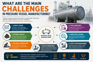
The main pressure vessel manufacturing challenges include incorrect material selection, design errors, welding defects, dimensional inaccuracies, inadequate non-destructive testing (NDT), pressure test failures, corrosion protection gaps and documentation or compliance shortfalls. Each affects containment safety, service life or delivery schedule, and each has a defined preventive control used during fabrication.
Pressure Vessel Manufacturing Challenges at a Glance
- Incomplete or incorrect design inputs delay engineering and create rework.
- Selecting the wrong material of construction shortens service life or causes early corrosion.
- Plate forming and dimensional errors create fit-up and installation problems.
- Welding defects compromise the pressure boundary and require repair.
- Loss of material and weld traceability weakens quality assurance.
- Choosing inadequate or incorrect NDT methods leaves defects undetected.
- Hydrostatic or pneumatic test failures point to unresolved fabrication issues.
- Corrosion, surface preparation and coating failures reduce vessel life.
- Code compliance, inspection and documentation gaps create acceptance risk.
- Cost overruns, rework and delivery delays result from poor stage control.
Understanding the Pressure Vessel Manufacturing Process
Pressure vessel manufacturing follows a defined sequence, and quality depends on controlling every stage rather than relying on the final test alone. This differs from general industrial metal fabrication, where dimensional tolerance and code compliance are usually less strict.
The typical process includes: design-input review, engineering calculations and drawing approval, material procurement and verification, plate cutting and edge preparation, rolling and forming, fit-up and dimensional checks, welding, NDT and stage inspection, post-weld heat treatment (PWHT) where required, hydrostatic or pneumatic testing, surface preparation and coating, and final documentation and dispatch.
Most pressure vessel manufacturing challenges trace back to a weakness introduced at one of these stages, such as an unrecorded material substitution or a skipped dimensional check, which is difficult to detect later and often surfaces only during hydrostatic testing or, worse, in service.
Challenge 1: Incomplete or Incorrect Design Inputs
Direct answer: Design-input errors happen when the datasheet is incomplete, design and operating conditions are confused, or drawings are revised after fabrication starts, leading to incorrect shell thickness and rework.
Why does design-input review fail?
Common issues include incorrect design pressure or temperature, a missing corrosion allowance, unclear fluid properties, an incomplete nozzle schedule, or missing wind and seismic load data found only during engineering review.
Confusing operating conditions with design conditions is a frequent error. Design pressure and temperature must include a margin above normal operating values; treating the two as identical understates the required shell thickness. Late revisions to an approved drawing are equally disruptive, forcing partial rework once cutting or forming has begun.
Consequences include incorrect shell thickness, insufficient nozzle reinforcement, unplanned rework, procurement delays and plant-integration problems.
Solution
An experienced fabrication team works from a design-input checklist before releasing drawings: a client-approved datasheet, P&ID review to confirm nozzle count and function, a confirmed nozzle schedule, material and corrosion-allowance review, confirmation of the applicable code edition, formal client approval of the GA drawing, and a documented change-control procedure for post-approval revisions.
Buyers should confirm that vessel orientation, nozzle placement and fluid characteristics were reviewed jointly with engineering before drawings were released, since selecting the right industrial pressure vessel configuration at this stage avoids downstream rework.
Challenge 2: Selecting the Wrong Material of Construction
Direct answer: Material of construction (MOC) selection fails when a material is chosen mainly on cost or availability rather than compatibility with the process fluid, temperature and corrosion allowance, which shortens vessel life below its intended design life.
Carbon steel suits non-corrosive, moderate-temperature applications, while stainless or alloy steel is generally required for corrosive chemicals, chloride-bearing fluids, hydrogen service or hygienic applications. Temperature limits, weldability and availability all factor into the decision. A material that looks cost-effective at procurement can create a higher lifecycle cost if it corrodes early or forces unplanned shutdowns.
Solution
Reliable selection involves a process-fluid compatibility review, an adequate corrosion allowance, and confirmation that the material is weldable and compatible with the intended PWHT cycle. Material Test Certificates (MTCs) are reconciled against the purchase specification, positive material identification (PMI) is applied where specified, heat-number traceability is maintained through fabrication, and any substitution requires client and code approval.
| Service Condition | Material Concern | Practical Control |
|---|---|---|
| Corrosive chemical service | Chloride stress corrosion, pitting | Corrosion allowance, alloy selection based on fluid chemistry |
| High-temperature service | Reduced allowable stress, creep | Design-code allowable stress tables, temperature-rated material |
| Hydrogen service | Hydrogen embrittlement, blistering | Material selection per applicable hydrogen-service guidance |
| Hygienic or food-grade service | Surface finish and cleanability | Stainless steel with specified finish and passivation |
| Low-temperature service | Brittle fracture risk | Impact-tested material where required by code |
Final material selection depends on engineering calculations, the applicable code and specific process conditions, so a single grade cannot be recommended for every application.
Challenge 3: Plate Forming and Dimensional Accuracy Problems
Direct answer: Dimensional inaccuracies such as incorrect rolling radius, ovality, shell mismatch or nozzle orientation errors occur when rolling, forming and fit-up are not checked at each stage, creating piping-connection and installation problems.
Common issues include incorrect rolling radius, shell ovality, mismatch between shell courses, dished-end mismatch, out-of-roundness, incorrect overall length, nozzle orientation errors, and saddle or leg misalignment. Welding-induced distortion can also shift dimensions that were correct at fit-up. A misaligned nozzle forces field rework of connected piping, and saddle misalignment creates uneven loading once the vessel is installed and filled.
Solution
Dimensional control depends on calibrated measuring tools, templates for critical dimensions, and stage-wise inspection rather than a single check at the end. A controlled rolling sequence, tack-weld verification and confirmation against the approved GA drawing reduce the risk of carrying an error forward. Nozzle orientation is verified before final welding, and a final dimensional report is issued as part of the manufacturing record.
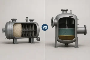
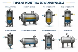
Horizontal, vertical, cylindrical and application-specific vessels each have different fabrication and support requirements, which is why buyers should understand the different types of pressure vessels relevant to their application before finalizing the design.
Challenge 4: Pressure Vessel Welding Defects
Direct answer: Pressure vessel welding defects such as porosity, lack of fusion, incomplete penetration and cracking typically result from incorrect parameters, contaminated joint surfaces or inadequate preheat, and they compromise the pressure boundary if not detected and repaired.
How can welding defects be prevented?
Common defects include porosity, slag inclusion, lack of fusion, incomplete penetration, undercut, cracking, burn-through, excessive reinforcement, arc strikes and welding-induced distortion. Recurring causes are incorrect welding parameters, contaminated joint surfaces, poor edge preparation, incorrect or damp consumables, inadequate preheat, inconsistent welder technique and uncontrolled interpass temperature. Because these defects directly affect the pressure boundary, pressure vessel welding defects are treated as a fabrication-stage risk rather than a cosmetic issue.
Solution
Weld quality is controlled through a qualified WPS, supported by a PQR and individual WPQ records for each welder assigned to pressure-boundary joints. Consumables are stored to prevent moisture pickup, preheat and interpass temperature are monitored where required, joint preparation and fit-up are inspected before welding, and the weld sequence is planned to reduce distortion on thick or large-diameter shells. Visual inspection after each stage, combined with weld mapping and documented repair records, allows any defect to be traced to its location and welder.
Challenge 5: Loss of Material and Weld Traceability
Direct answer: Traceability is lost when heat numbers are not transferred during plate cutting, part separation or nozzle fabrication, weakening the quality assurance chain for pressure-boundary components that must trace back to their original material certificate.
Traceability can break down during plate cutting, forming, consumable handling, nozzle fabrication, repair work, or an undocumented substitution. Because a vessel’s shell and nozzles are pressure-boundary components, each piece must stay traceable to its original Material Test Certificate throughout fabrication.
Solution
Traceability is maintained through a documented material identification procedure that transfers the heat number to every cut piece before separation, MTC reconciliation, weld maps recording joint location and welder, consumable batch records, and stage-wise documentation retained through dispatch.
Essential Traceability Records
- Material Test Certificates for plates, nozzles and fittings.
- Heat-number transfer records for every cut piece.
- Weld maps identifying joint location, welder and repair history.
- Welder identification and qualification records.
- Consumable batch and storage records.
- Stage-wise inspection sign-offs.
Challenge 6: Choosing Inadequate NDT or Applying It Incorrectly.
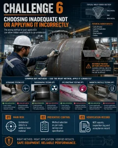
Direct answer: NDT fails to catch defects when the method chosen does not match the material, weld type or defect it needs to detect, since visual, dye penetrant, magnetic particle, ultrasonic and radiographic testing each detect different defect categories.
Which NDT method should be used?
Visual testing catches surface-level issues such as undercut. DPT detects surface-breaking discontinuities on non-porous materials, MPT finds surface and near-surface defects on ferromagnetic materials, UT evaluates internal weld integrity, and RT provides a volumetric image to detect porosity, inclusions and incomplete penetration. No single method covers every defect type, which is why pressure vessel inspection and testing typically combines more than one method depending on joint type, thickness and code requirement.
Solution
NDT selection is based on material, weld type, thickness, applicable code and project specification, not applied uniformly across every joint. It is carried out by qualified personnel following approved procedures, at the correct fabrication stage, against defined acceptance criteria. Any indication outside the criteria triggers repair and re-examination, and third-party witness points are scheduled where the inspection and test plan requires them. Full radiography is not a universal requirement for every pressure vessel; the extent of RT depends on the applicable code, joint category and client specification.
Challenge 7: Hydrostatic or Pneumatic Test Failures
Direct answer: Pressure testing failures usually trace back to weld or nozzle leakage, defective temporary closures, incorrect test pressure or trapped air rather than the test itself, which is why testing cannot compensate for incomplete NDT or poor fabrication.
What causes a pressure vessel to fail hydro testing?
A vessel can fail testing due to weld or nozzle leakage, defective temporary closures, incorrect test pressure, inadequate venting, trapped air, a faulty gauge, poor test preparation, dimensional movement, or incomplete NDT beforehand. In most cases, the test is revealing a fabrication issue that should have been caught earlier.
Pneumatic testing carries greater stored-energy risk than hydrostatic testing because compressed gas releases energy more suddenly if a failure occurs, which is why it is used only where hydrostatic testing is impractical and with added precautions.
Solution
Pressure testing is carried out against an approved procedure, using calibrated gauges and the correct test medium. Pressurization is controlled in stages, venting is completed beforehand, and an exclusion zone is established around the vessel. Inspection hold points, continuous leak monitoring and a documented acceptance criterion are standard parts of a controlled test, with results recorded in a formal test report.
Pressure testing must be planned and supervised by competent personnel in accordance with the applicable code, approved procedure and site-safety requirements.
Compressed-air receivers illustrate this discipline in practice: air receiver vessel manufacturing requires the same controlled welding, NDT, traceability and pressure testing as a process pressure vessel, even though the application is utility rather than process service.
Challenge 8: Corrosion, Surface Preparation and Coating Failures
Direct answer: Coating and corrosion problems occur when surface preparation does not meet the specified standard, the coating system is mismatched to the environment, or the base material was already unsuitable, meaning coating cannot correct a poor material choice.
Corrosion risk comes from internal corrosion caused by the process fluid, external atmospheric corrosion, chemical attack, crevice corrosion at flanged joints, and chloride-related concerns. On the coating side, poor surface preparation, an incorrect coating system, inadequate dry-film thickness (DFT), or transport damage all shorten protective life.
Solution
Corrosion control starts with correct material selection, an adequate corrosion allowance, and, where specified, an internal lining suited to the process fluid. Surface preparation follows the specified standard before a compatible coating is applied, with DFT verified by inspection rather than assumed. Drainage design that avoids standing liquid, transport protection and preservation before installation extend coating life. Coating cannot correct an unsuitable base-material selection; these are separate decisions made at different project stages.
Challenge 9: Code Compliance, Inspection and Documentation Gaps
Direct answer: Documentation gaps arise when the applicable code edition is misapplied, the Quality Assurance Plan (QAP) or Inspection and Test Plan (ITP) is incomplete, or weld repairs and deviations go unrecorded, creating acceptance risk at final inspection.
Common gaps include applying an outdated code edition, an incomplete QAP or missing ITP, unapproved deviations from the approved drawing, missing NDT reports or MTCs, missing calibration records, unrecorded weld repairs, and an incomplete Manufacturing Data Record (MDR) at dispatch. It is worth distinguishing manufacturing code requirements from additional client-specification requirements, third-party inspection requirements set by the purchase order, and in-service inspection requirements that apply after installation.
Solution
A compliance matrix mapping code, client specification and inspection requirements is established early, along with a document-submission schedule. The QAP and ITP are approved before fabrication begins, with inspection hold and witness points scheduled accordingly. Any deviation from the approved drawing goes through formal approval rather than being resolved informally on the shop floor, and the MDR is reviewed against a document index before dispatch.
Where a project specifies ASME BPVC Section VIII as the applicable design code, fabrication and inspection follow that code’s construction rules, but not every vessel requires a formal ASME certification stamp; this depends on the client specification, jurisdiction and contractual scope.
Challenge 10: Cost Overruns, Rework and Delivery Delays
Direct answer: Schedule and cost overruns typically stem from incomplete drawings, late client changes, rejected welds or delayed inspection calls rather than the fabrication work itself, and each is manageable with earlier planning and stage-gate control.
Recurring causes include incomplete drawings at fabrication start, material shortages, late client-driven changes, rejected welds requiring repair, delayed inspection calls, subcontractor coordination gaps, unplanned PWHT requirements, an incorrect Bill of Materials (BOM), and dispatch-stage documentation delays.
Solution
A design freeze before fabrication begins, combined with disciplined procurement planning, reduces the risk of late changes disrupting the schedule. A realistic production schedule with material-status tracking and an inspection notification plan keeps hold points from becoming bottlenecks. Stage-gate quality checks catch problems before they compound, a formal change-order process prevents undocumented scope changes, and early coordination with third-party inspection (TPI) agencies keeps dispatch on track.
Buyers evaluating a custom fabrication partner should review how engineering, fabrication, inspection and delivery are planned together, since schedule risk usually comes from gaps between these functions rather than within any single one.
Challenge-versus-Solution Summary Table
How a Strong Pressure Vessel Quality-Control System Prevents Failures
Pressure vessel quality control is not a single inspection step; it is a set of checks distributed across the fabrication sequence.
Before Fabrication
Drawing and datasheet review, material verification, WPS/PQR/WPQ review for assigned welders, QAP and ITP approval with the client or TPI agency, and calibration checks on measuring tools and gauges.
During Fabrication
Fit-up inspection before welding, in-process weld monitoring, ongoing material and weld traceability, stage-wise dimensional checks, NDT at defined hold points, and repairs carried out under an approved procedure.
Before Dispatch
Final NDT and review of outstanding indications, hydrostatic or pneumatic pressure testing, surface and coating inspection, final dimensional report, compilation of the Manufacturing Data Record, and packing and preservation for transport.
Heavy engineering fabrication capability depends on more than equipment; it also depends on qualified manpower, inspection discipline and coordinated project management across these three stages, which is part of what buyers should assess when reviewing heavy engineering fabrication capability.
Manufacturing Documents Buyers Should Request
Before accepting delivery, buyers should request: approved GA drawing; design calculations, where included in scope; Material Test Certificates; material traceability records; weld map; WPS/PQR/WPQ records as contractually required; NDT reports; PWHT chart, where applicable; dimensional inspection report; hydrostatic or pneumatic test report; coating inspection report; calibration certificates; third-party inspection release note, where applicable; Manufacturing Data Record; and dispatch clearance documentation.
The final package depends on the applicable code, the purchase order and the agreed inspection scope, so not every project requires every item on this list.
How to Select a Reliable Pressure Vessel Manufacturer
Among the many pressure vessel manufacturers in India, buyers benefit from evaluating capability against a consistent set of criteria rather than comparing quotations alone. The list above of common pressure vessel manufacturing challenges gives a practical basis for this evaluation.
Relevant criteria include fabrication experience with the applicable vessel type and code, engineering-review capability, a controlled material-handling and traceability system, qualified welding procedures, coordinated NDT capability, in-house and third-party inspection support, dimensional-control capability, documentation discipline, customization capability, a realistic production schedule, clearly stated scope exclusions, and responsive post-order communication. A manufacturer strong in welding but weak in documentation still creates acceptance risk at dispatch.
Why Custom Pressure Vessel Manufacturing Helps Solve Application-Specific Challenges
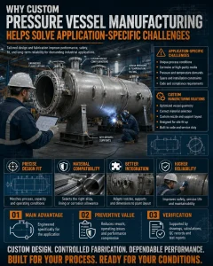
Custom pressure vessel manufacturing becomes necessary when standard configurations cannot meet a project’s specific requirements. This typically applies to non-standard pressure and temperature combinations, unique fluid service, special nozzle arrangements, skid-mounted integration, limited plant space, a specific orientation, custom internals, corrosion-resistant material requirements, mandatory third-party inspection, special coating or lining systems, and project-specific documentation formats.
Based on project specifications and inspection requirements, an experienced fabrication team typically works from the client’s drawings, datasheet, duty conditions and inspection expectations to develop a vessel that meets both the process requirement and the applicable code. National Engineers & Steel Fabricators manufactures custom pressure vessels on this basis, using client-supplied drawings, datasheets, duty conditions and inspection requirements as the starting point for engineering review.
Conclusion
Most pressure vessel manufacturing challenges begin well before the first weld is struck. Incomplete design inputs, an unsuitable material choice or a skipped dimensional check at fit-up tend to surface later as welding defects, failed hydrostatic tests or documentation gaps at dispatch. Correct inputs, qualified materials, controlled welding procedures, staged inspection and complete documentation address these risks at the point they are created rather than after the fact.
Final testing remains an important checkpoint, but it cannot replace stage-wise quality control across the manufacturing sequence. Buyers evaluating a fabrication partner should weigh engineering discipline, traceability, welding quality and documentation alongside price, since a lower quotation that skips stage-wise inspection often costs more in rework, delay or premature failure.
Share your pressure vessel drawings, datasheet, material requirements, design conditions, NDT scope and inspection expectations with National Engineers & Steel Fabricators for a technical and commercial review.
This article is intended for general technical guidance. Final design, fabrication and testing requirements depend on the applicable design code, service conditions, client specifications and review by a competent, authorized engineer.
Frequently Asked Questions
What causes welding defects in pressure vessels?
Welding defects usually result from incorrect welding parameters, contaminated joint surfaces, poor edge preparation, incorrect or damp consumables, inadequate preheat, inconsistent welder technique, or uncontrolled interpass temperature. A qualified WPS, verified PQR, and individually qualified welders (WPQ) reduce this risk, along with fit-up inspection and stage-wise visual checks.
How can pressure vessel manufacturing defects be prevented?
Manufacturing defects are prevented through stage-wise control rather than a single final inspection: design-input verification, material traceability, qualified welding procedures, dimensional checks at each forming and fit-up stage, and NDT at defined hold points. Defects caught early are corrected through documented repair and re-inspection before proceeding to the next stage.
Why is material selection important in pressure vessel manufacturing?
Material selection determines how a vessel performs against its process fluid, operating temperature and corrosion allowance over its service life. A material chosen mainly for cost or availability, without checking compatibility, weldability and code-allowable stress, can corrode early or fail to meet design margins, creating higher lifecycle cost.
Which NDT methods are used for pressure vessel inspection?
Visual testing, dye penetrant testing (DPT), magnetic particle testing (MPT), ultrasonic testing (UT) and radiographic testing (RT) are the methods commonly used. Each detects different defect types, so selection depends on the material, joint type, thickness and applicable code, rather than applying one method uniformly to every weld.
What causes a pressure vessel to fail a hydrostatic test?
Common causes include weld or nozzle leakage, defective temporary closures, incorrect test pressure, inadequate venting, trapped air, a faulty pressure gauge, poor test preparation, or incomplete NDT before testing. In most cases, the result reflects a fabrication issue that an earlier inspection stage should have identified.
What documents should a pressure vessel manufacturer provide?
Typical documents include the approved GA drawing, Material Test Certificates, traceability records, weld map, WPS/PQR/WPQ records, NDT reports, PWHT chart where applicable, dimensional and pressure test reports, coating inspection report, calibration certificates and the Manufacturing Data Record. The exact package depends on the applicable code and purchase order.
What is the role of ASME Section VIII in pressure vessel manufacturing?
ASME BPVC Section VIII sets construction rules for pressure vessel design, materials, fabrication and inspection when specified as the applicable code. Not every vessel requires a formal ASME certification stamp; whether a stamp is required depends on the client specification, jurisdiction and contractual scope, so this should be confirmed at the design-input stage.
How do I select a reliable pressure vessel manufacturer in India?
Evaluate fabrication experience with the relevant vessel type and code, engineering-review capability, material traceability systems, qualified welding procedures, NDT and inspection coordination, documentation discipline, customization capability, and a realistic production schedule. Comparing these criteria together, rather than quotation price alone, gives a more reliable picture of manufacturing risk.
Can pressure vessels be manufactured according to client drawings?
Yes. Custom pressure vessel manufacturing is based on the client’s approved drawings, datasheet, duty conditions and inspection requirements. An experienced fabrication team reviews these inputs against the applicable design code before releasing drawings for fabrication, adjusting nozzle arrangement, internals or coating as the application requires.