Steel fabrication quality control cannot be treated as a single inspection performed after a component is welded and painted. By the time a finished vessel, tank, or structural assembly reaches the final inspection stage, most of the decisions that determine its reliability have already been made.
Quality has to be planned before the first plate is cut, and it has to be verified at every stage that follows: design review, material procurement, cutting, forming, fit-up, welding, inspection, surface preparation, testing, documentation, and dispatch.
When any one of these stages is skipped or poorly controlled, the consequences show up later, usually at the worst possible time. Dimensional mismatch, poor fit-up, weld defects, mixed-up materials, and reduced structural integrity are common outcomes of weak in-process control.
So are leakage, premature corrosion, installation delays at site, unplanned rework, higher project costs, and in the worst cases, safety and compliance risks that surface only after equipment is put into service.
This article walks through how steel fabrication quality control actually works on the shop floor, stage by stage, using examples from pressure vessels, storage tanks, process equipment, structural assemblies, platforms, and piping supports.
| Steel fabrication quality control is the planned inspection, testing, verification and documentation used to confirm that fabricated steel components meet approved drawings, material specifications, dimensional tolerances, welding requirements and applicable project standards. |
An effective quality-control system is never just an inspection checklist. It combines preventive controls built into the process, in-process inspection at defined stages, and documented verification that ties every finished component back to its drawing, material, and procedure.
What Is Quality Control in Steel Fabrication?
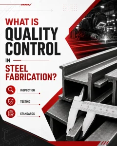
Quality control in steel fabrication refers to the operational checks used to confirm that a fabricated component conforms to its approved drawing, material specification, and applicable code requirements at each stage of production.
It is distinct from a one-time final check. Quality control activities are distributed across the entire fabrication process, and each activity is intended to catch a specific class of error before it becomes locked into the next stage.
- Material verification against the purchase order and Material Test Certificate
- Drawing and revision review before cutting or welding begins
- Stage inspection during cutting, forming, and fit-up
- Welding inspection, including visual checks and parameter monitoring
- Dimensional measurement against approved tolerances
- Non-destructive testing (NDT) of welds where specified
- Coating and surface-finish inspection
- Functional or pressure testing where applicable
- Documentation review before final release
Treating inspection as a final-stage activity is one of the most common and costly mistakes in industrial fabrication. By the time a defect is found at the end, the item may need partial disassembly, cutting out a weld, or reworking a coated surface.
Quality Assurance vs Quality Control in Steel Fabrication
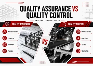
Quality assurance and quality control are related but not interchangeable. Confusing the two is common, and it leads to gaps where neither the system nor the product is actually being checked.
Quality Assurance
Quality assurance is the system that is put in place to prevent problems before fabrication starts. It is process-oriented rather than product-oriented.
- Documented quality plans and procedures
- Approved vendor and sub-supplier lists
- Welder qualification and certification records
- Calibration systems for measuring and test equipment
- Document control procedures for drawings and specifications
- Internal audits of the fabrication process
- Training records for production and inspection personnel
- Material traceability procedures
Quality Control
Quality control verifies the actual fabricated product against the requirements set by the quality assurance system. It is product-oriented and happens throughout production.
- Incoming material inspection
- Dimensional checks at defined stages
- Visual and instrumented weld examination
- Non-destructive testing of completed welds
- Coating thickness and adhesion checks
- Pressure or leak testing
- Final inspection before dispatch
Quality Assurance vs Quality Control at a Glance
| Parameter | Quality Assurance | Quality Control |
|---|---|---|
| Main purpose | Prevent defects by building a controlled system | Detect and verify conformance in the actual product |
| Timing | Before and throughout the project | During and after specific production stages |
| Typical activities | Procedures, welder qualification, calibration systems, audits | Material inspection, weld inspection, NDT, dimensional checks |
| Responsibility | Quality manager, engineering, management systems | QC inspectors, welding inspectors, NDT technicians |
| Records generated | Quality plan, procedures, qualification records, audit reports | Inspection reports, NDT reports, dimensional reports, test certificates |
| Example in fabrication | Approving a Welding Procedure Specification before production | Visually inspecting a completed weld against that same procedure |
Why Is Quality Control Important in Industrial Steel Fabrication?
Quality control in steel fabrication affects far more than whether a component looks acceptable at handover. It has a direct bearing on safety, structural integrity, and how the equipment performs once it is installed and placed into service.
A pressure vessel with an undetected weld defect carries a containment risk. A storage tank with poor dimensional control may not seat correctly on its foundation. A structural assembly with excessive distortion can create load-path problems that are difficult to correct on site.
Quality control also has a direct effect on project schedules and total lifecycle cost. Rework, site modification, and delayed commissioning are almost always more expensive than the in-process controls that would have prevented them.
A practical example: a vessel nozzle fabricated at the wrong orientation can still pass a basic visual check, since the weld itself may look sound. The real problem only appears at site, when the connecting pipework does not align, forcing rework that a simple dimensional check during fabrication would have prevented.
Also Read: Custom Pressure Vessels
Develop a Project-Specific Inspection and Test Plan
An Inspection and Test Plan, commonly called an ITP, is a document that defines exactly what will be inspected, when, by whom, and against which acceptance criteria for a specific fabrication project.
A well-structured ITP typically identifies inspection stages, applicable drawings and procedures, acceptance criteria, responsible parties, and the records that must be generated at each stage.
- Hold point: fabrication cannot proceed past this stage until the inspection is completed and formally released
- Witness point: the inspecting party is notified and may attend, but fabrication can continue if they do not attend
- Surveillance point: general monitoring during production without a scheduled stop
- Document-review point: verification is done by reviewing records rather than physically inspecting the item
The ITP should be reviewed and approved according to the specific requirements of each project before fabrication progresses. An ITP written for one pressure vessel order is not automatically valid for a different project, even one with a similar design.
Review Drawings, Specifications and Design Inputs Before Fabrication
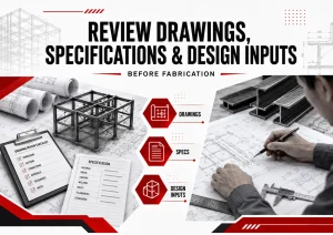
Before any cutting or welding begins, the fabrication team needs to review the complete design package: approved fabrication drawings, general arrangement drawings, detail drawings, and the bill of materials.
This review also covers material specifications, weld details, dimensional tolerances, surface-finish requirements, NDT requirements, heat-treatment requirements, the specified coating system, and any client-specific technical requirements.
Design-input problems are more common than many buyers assume, and catching them before fabrication starts is far cheaper than catching them afterward.
- Missing dimensions or conflicting notes between drawing views
- Incorrect or ambiguous material references
- Unclear weld symbols or joint details
- Missing tolerances for critical dimensions
- Incomplete nozzle orientation information on vessel drawings
- Mismatch between the drawing revision in hand and the latest approved revision
- Unapproved design changes communicated informally rather than through a controlled process
Document revision control matters here: fabrication should always proceed against the current approved revision, with older revisions clearly marked as superseded and withdrawn from the shop floor.
Verify Raw Materials Before Production
Incoming-material inspection is the first product-level quality control activity in the fabrication sequence, and it needs to happen before any material is released to cutting.
- Material grade against the purchase order and specification
- Plate thickness and overall dimensions
- Surface condition, including visible damage or corrosion
- Quantity received against the order
- Heat number and its match to the Material Test Certificate (MTC)
- Manufacturer identification and markings
- Physical damage from transport or handling
- Lamination or other visible surface defects where relevant to the material type
Fabrication should not begin on material that cannot be positively identified or verified against its documentation. Unidentified material creates a traceability gap that cannot be closed later, no matter how good the fabrication work is.
Also Read: Vertical Storage Tanks
Maintain Material Traceability Throughout Fabrication
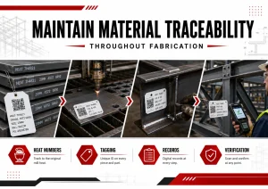
Material traceability in fabrication means being able to link every finished component back to the specific heat of steel it was made from, supported by the Material Test Certificate for that heat.
- Heat-number identification carried on each plate, pipe, or section
- Material Test Certificates matched to heat numbers
- Traceability logs maintained as material moves through the shop
- Cutting plans that record which heat each cut piece came from
- Heat-number transfer to smaller pieces before original markings are cut away
- Part marking that survives forming, blasting, and machining
- MTC reconciliation against the as-built parts list
- Material segregation to prevent mix-ups between similar-looking grades
- Positive Material Identification (PMI) using portable analysers where specified
Traceability is most at risk during operations that remove or obscure the original markings: cutting, shot blasting, forming, rolling, machining, assembly, and any subsequent rework.
Identification needs to be transferred to the new piece before the original marked section is cut away or blasted off, not after. Once that link is broken, it generally cannot be reliably reconstructed.
| Material quality cannot be reliably demonstrated if the material loses its identity during fabrication. |
Control Material Storage and Handling
Correct material can still be damaged or degraded by poor storage and handling long before it reaches the cutting table.
- Protection from moisture and standing water
- Correct plate stacking to avoid distortion under self-weight
- Controlled lifting to prevent bending or surface gouging
- Separation of carbon steel and stainless steel storage areas
- Prevention of iron contamination on stainless surfaces
- Edge protection during transport and stacking
- Controlled storage of welding consumables away from moisture
- Identification retained and legible after storage
- First-in, first-out (FIFO) stock rotation where shelf life or ageing is relevant
Where contamination control is required, stainless steel handling should use dedicated tools, slings, and storage racks that are never used for carbon steel.
Ensure Accuracy During Cutting and Edge Preparation
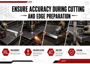
Cutting and edge preparation set the foundation for everything that follows, particularly fit-up and weld quality. This applies whether the process is plasma cutting, gas cutting, laser cutting, saw cutting, shearing, or machining.
- Overall dimensions against the approved drawing and current revision
- Squareness of cut edges
- Edge quality and cut profile
- Bevel angle and root face for weld preparation
- Heat-affected zone condition, particularly for thermal cutting processes
- Slag and burr removal before the piece moves to the next stage
Incorrect edge preparation is a frequent root cause of fit-up problems downstream, including excessive root gaps, poor bevel angles, and weld joints that need field correction before they can be welded within procedure.
Control Forming, Rolling and Bending Operations
Plate rolling, head forming, section bending, and press forming all introduce dimensional and metallurgical variables that need to be controlled, not just measured after the fact.
- Forming sequence and number of passes
- Minimum bend radius for the material and thickness
- Plate orientation relative to rolling direction
- Thickness reduction during forming
- Ovality and diameter for rolled cylindrical sections
- Straightness after forming
- Spring-back allowance
- Surface damage from rolls or tooling
- Temperature control for hot-forming operations
- Re-identification of the piece after forming, if original markings are affected
Certain materials and thicknesses require special forming procedures, controlled temperatures, or post-forming heat treatment. What applies to one plate thickness and grade will not automatically apply to another.
Maintain Proper Fit-Up and Assembly Control
Fit-up inspection happens before welding starts, while the joint is still accessible and any misalignment can still be corrected without cutting into a completed weld.
- Joint alignment and root gap
- Hi-low or internal mismatch across the joint
- Tack-weld quality and placement
- Component orientation, including nozzle location on vessels
- Flange alignment
- Squareness and level of structural members
- Removal of temporary attachments where required
- Joint cleanliness before welding
- Dimensional tolerances specific to the joint type
Poor fit-up is a direct contributor to lack of penetration, distortion, misalignment, excessive weld volume, and downstream installation problems. Fit-up should always be inspected and signed off before the joint becomes inaccessible.
Use Qualified Welding Procedures and Welders
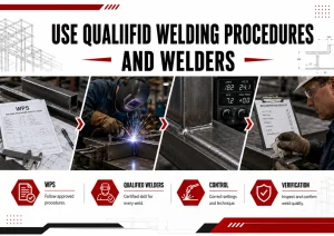
Welding quality control in industrial fabrication depends on three linked documents: the Welding Procedure Specification (WPS), the Procedure Qualification Record (PQR), and Welder Performance Qualification (WPQ) records.
The WPS defines exactly how a joint is to be welded, and it needs to specify parameters that the welder and the inspector can both check against.
- Base material and filler material
- Welding process and joint design
- Welding position
- Current, voltage, and travel speed ranges
- Heat input limits
- Preheat and interpass temperature requirements
- Shielding gas type and flow rate
- Post-weld heat treatment, where applicable
Welders and welding operators must be qualified for the specific process, position, joint type, and material range they are assigned to. A welder qualified for one joint configuration is not automatically qualified for a different one.
Control Welding Consumables
Filler metals and shielding gases need their own control system, since incorrect or poorly handled consumables can undermine an otherwise correct welding procedure.
- Correct filler-metal classification for the joint
- Batch identification and traceability
- Storage conditions and holding ovens
- Baking requirements and exposure-time limits after removal from the oven
- Moisture control, particularly for low-hydrogen electrodes
- Issue and return records
- Segregation and disposal of damaged consumables
- Shielding gas identification and quality
Poorly controlled consumables are a known contributor to hydrogen cracking, porosity, reduced weld mechanical properties, and inconsistent weld performance across a project.
Monitor Welding Parameters During Production
In-process welding control means checking that actual parameters stay within the range defined by the qualified WPS, not just checking the finished weld afterward.
- Amperage, voltage, and travel speed
- Heat input calculation
- Preheat and interpass temperature
- Welding sequence
- Interpass cleaning between weld passes
- Back gouging and root protection where specified
- Shielding gas flow rate
- Environmental conditions such as wind and moisture affecting the weld pool
Parameters drifting outside the qualified WPS range, even without an immediately visible defect, can affect weld metallurgy and mechanical properties in ways that only show up under load or in service.
Prevent and Control Welding Distortion
Distortion in welded steel structures results from uneven heating and cooling during welding, and it is generally easier to prevent than to correct after the fact.
- Balanced and symmetrical welding sequences
- Back-step welding technique
- Controlled heat input
- Strongbacks and fixtures to hold alignment during welding
- Presetting components to compensate for expected shrinkage
- Intermittent welding where the design permits it
- Correct tack-welding practice
- Controlled, procedure-based repair rather than ad-hoc correction
- Stage-wise dimensional checks to catch distortion early
Excessive mechanical straightening or uncontrolled local heating to correct distortion should never be carried out without an approved procedure, since it can introduce new stresses or metallurgical changes.
Perform Visual Inspection at Every Welding Stage
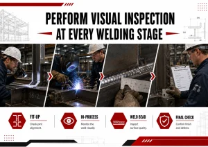
Visual inspection is the most frequently used weld quality control tool, and it needs to happen before, during, and after welding, not only once the joint is complete.
Before Welding
- Joint preparation and fit-up
- Cleanliness of the joint
- Consumable condition
- Welder identity and current qualification
- WPS availability at the workstation
- Preheat where required
During Welding
- Welding parameters against the WPS
- Interpass cleaning
- Interpass temperature
- Welding sequence
- Arc strikes outside the joint
- Any visible defects as welding progresses
After Welding
- Weld size and profile
- Undercut and overlap
- Surface cracks
- Porosity
- Spatter
- Arc strikes
- Incomplete filling
- Other surface irregularities
Visual inspection forms the first layer of weld quality control, but it does not replace non-destructive testing on joints where NDT is specified, since many internal defects are simply not visible from the surface.
Select the Correct NDT Method
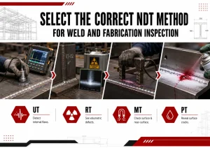
Non-destructive testing (NDT) in steel fabrication needs to be selected based on the material, joint type, expected defect type, weld geometry, thickness, accessibility, and the applicable project specification.
Visual Testing (VT)
Visual testing is the baseline method for every weld and checks for surface-level defects such as undercut, overlap, and incomplete filling. It cannot detect internal or subsurface discontinuities.
Dye-Penetrant Testing (PT)
Dye-penetrant testing is suitable for detecting surface-breaking defects such as cracks and porosity on non-porous materials, including many stainless steel welds. It does not detect subsurface flaws.
Magnetic-Particle Testing (MT)
Magnetic-particle testing is used on ferromagnetic materials to find surface and near-surface defects that may not be visible to the naked eye. It is not applicable to non-magnetic materials such as austenitic stainless steel.
Ultrasonic Testing (UT)
Ultrasonic testing examines internal discontinuities and can also verify material thickness. It requires trained personnel to interpret results correctly and is commonly used on thicker sections and pressure-retaining welds.
Radiographic Testing (RT)
Radiographic testing provides volumetric examination of selected welds and is often specified for critical pressure-vessel and piping joints. It requires radiation safety controls and qualified interpretation of the film or digital image.
No single NDT method detects every type of defect, which is why project specifications often call for a combination of methods depending on the criticality of the joint.
- Personnel qualified to the relevant NDT method and level
- Approved written procedures for each method
- Calibrated equipment with current calibration records
- Defined acceptance criteria tied to the applicable code
- Formal NDT reports retained as part of the manufacturing record
- A clear path for repair and re-examination of rejected indications
Control Weld Repairs Properly
Weld repairs need to follow the same level of control as the original weld, and should never be carried out informally by whichever welder is available.
- Defect identification and location recording
- Formal repair approval before work starts
- Complete defect removal, verified before rewelding
- Excavation inspection to confirm the defect is fully removed
- Use of an approved repair procedure
- Assignment to a qualified welder
- Rewelding within the qualified parameters
- Repeat NDT on the repaired area
- Repair history recorded against the component
- Additional review where a joint requires multiple repairs
Uncontrolled repairs can introduce new defects, alter local metallurgy, or break the traceability link between the finished weld and its original qualification records.
Perform Stage-Wise Dimensional Inspection
Dimensional inspection catches errors while they are still correctable, rather than after they have been built into the final assembly.
- Length, width, and height
- Diameter and circumference for cylindrical components
- Ovality and straightness
- Flatness and squareness
- Nozzle orientation and flange alignment
- Hole location and support positions
- Centreline and elevation references
- Overall assembly dimensions
Measuring tapes, vernier calipers, micrometers, levels, templates, and straight edges cover most routine checks, while total stations or laser instruments may be used for larger structural assemblies where precision alignment is critical.
Every measurement should be checked against the tolerance approved for that specific project and drawing, since acceptable tolerances vary by component type, code, and client requirement.
Use Calibrated Inspection and Testing Equipment
Measurements are only as reliable as the equipment used to take them, which is why calibration control is a core part of steel fabrication quality control.
- Welding machines, where output monitoring is required
- Pressure gauges used in testing
- Measuring tapes, vernier calipers, and micrometers
- Temperature indicators
- Coating-thickness gauges and holiday detectors
- NDT instruments
- Torque tools where used in assembly
Equipment identification, calibration status labels, and traceability to recognized calibration standards all need to be maintained. If equipment is later found to be out of calibration, previous measurements taken with it need to be reassessed.
Control Surface Preparation and Coating Quality
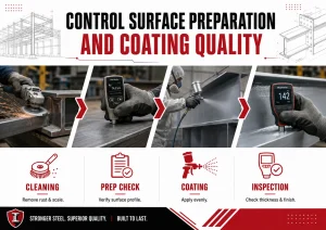
Coating performance depends heavily on how well the surface was prepared before the coating was applied, more than on the coating product itself.
- Degreasing and cleaning before blasting
- Rust and mill-scale removal
- Abrasive blasting to the specified surface profile
- Dust removal after blasting
- Environmental conditions, including relative humidity and dew point
- Surface temperature during application
- Primer application and recoat interval
- Dry-film thickness measurement
- Holiday testing where specified
- Adhesion testing where specified
- Coating repair procedures
Common coating defects such as blistering, pinholes, poor adhesion, runs, sagging, undercuring, and insufficient or excessive film thickness are almost always traceable back to a surface-preparation or environmental-control lapse.
Manage Stainless-Steel Fabrication Quality
Stainless steel fabrication needs its own set of controls, because contamination and heat effects that would not matter on carbon steel can compromise corrosion resistance on stainless materials.
- Material segregation from carbon steel throughout the shop
- Dedicated tools and grinding wheels
- Controlled grinding to avoid embedding foreign particles
- Use of abrasives suitable for stainless steel
- Cleaning procedures free of chloride contamination
- Pickling and passivation where specified
- Back purging during welding to control internal oxidation
- Heat-tint control and removal after welding
- Surface finish appropriate to the service condition
- Handling and storage that avoids contact with carbon-steel tools or surfaces
Stainless steel that has been contaminated with iron particles or exposed to chlorides can corrode in service even though the base material itself met specification at the time of receipt.
Also Read: Filter Vessels
Conduct Pressure, Leak or Functional Testing Where Applicable
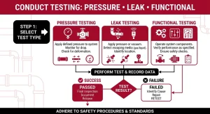
Testing requirements depend on the equipment type and the approved test procedure for that specific project; not every fabricated item requires pressure testing.
- Hydrostatic testing
- Pneumatic testing where explicitly permitted
- Leak testing
- Vacuum testing
- Load testing
- Trial assembly
- Functional checks
For pressure testing specifically, the approved procedure needs to define the test pressure, use calibrated gauges, control venting and filling, allow pressure stabilization, and define a safety exclusion zone during the hold period.
Pneumatic testing carries a materially higher stored-energy risk than hydrostatic testing, since compressed gas releases energy far more violently than water in the event of a failure, and it requires strict engineering and safety controls when it is used.
Also Read: Air Receiver Vessels Manufacturer
Maintain Strong Document Control
Quality documentation is part of the deliverable, not paperwork produced alongside it. A fabricated component without complete records cannot be fully verified even if the physical item appears correct.
- Approved drawings and the drawing revision register
- Inspection and Test Plan (ITP) and quality plan
- WPS, PQR, and welder qualification records
- Material Test Certificates and traceability records
- Weld maps
- NDT reports
- Dimensional inspection reports
- Calibration certificates
- Heat-treatment charts where applicable
- Coating inspection reports
- Pressure-test reports
- Non-conformance reports
- Repair records
- Final inspection release documentation
- The manufacturing data book compiled at project close-out
Manage Non-Conformances and Corrective Actions
A non-conformance is any deviation from an approved drawing, specification, procedure, or acceptance criterion identified during fabrication or inspection.
- Identify the issue
- Record the non-conformance formally
- Segregate or mark the affected item to prevent unintended further processing
- Evaluate the impact on fit, function, and applicable requirements
- Decide on disposition
- Obtain the necessary approval for that disposition
- Perform repair, rework, use-as-is approval, or rejection as decided
- Re-inspect the item against the original or revised acceptance criteria
- Identify the root cause of the non-conformance
- Implement corrective action to address that root cause
- Verify that the corrective action was effective
A correction fixes the specific item in front of you. Corrective action addresses the underlying cause so the same problem does not recur elsewhere in the project. Preventive control is put in place before a similar issue can occur at all.
Conduct Final Inspection Before Dispatch
Final inspection verifies both product conformity and dispatch readiness, and it should be the last gate before a component leaves the fabrication shop.
- Overall dimensions and component completeness
- Weld condition
- Surface finish and coating condition
- Identification marking and nameplate data where applicable
- Nozzle and flange protection
- Internal cleanliness and removal of loose items
- Documentation completeness
- Packing arrangement
- Lifting points and transportation supports
Also Read: Blowdown and Flash Tanks
Protect Fabricated Equipment During Packing and Transportation
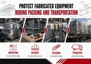
Equipment that has passed final inspection can still be damaged in transit, which undermines the quality effort already invested in it.
- Flange covers and nozzle protection
- Moisture and coating protection
- Internal preservation where required
- Transit supports and secured lifting lugs
- Centre-of-gravity marking for large components
- Securing of any loose or removable parts
- Clear handling instructions for the receiving site
Also Read: Water Holding Utility Vessels
Steel Fabrication Quality-Control Checklist
The following checklist summarizes typical risks and controls across the fabrication sequence. It is a general reference; a project-specific ITP always takes precedence.
Stage-Wise Quality Control Checklist
| Fabrication Stage | Quality Risk | Preventive Control | Inspection / Verification | Quality Record |
|---|---|---|---|---|
| Design-input review | Missing or conflicting drawing data | Structured drawing and spec review | Design review checklist | Review sign-off |
| Material procurement | Wrong grade or spec ordered | Approved vendor list, PO verification | PO vs specification check | Purchase order |
| Material receipt | Unverified or damaged material | Incoming inspection procedure | Visual and MTC check | Material receipt report |
| Traceability | Loss of heat-number identity | Marking transfer procedure | Traceability log audit | Traceability log |
| Cutting | Dimensional or edge-prep error | Qualified cutting procedure | Dimensional and edge check | Cutting inspection record |
| Forming | Distortion, thickness reduction | Controlled forming procedure | Dimensional check post-forming | Forming report |
| Fit-up | Misalignment, root-gap error | Fit-up procedure and tolerances | Fit-up inspection | Fit-up report |
| Welding | Weld defects, parameter drift | Qualified WPS, trained welders | In-process monitoring | Welding log |
| Consumable control | Hydrogen cracking, porosity | Baking, storage, issue control | Consumable issue check | Consumable log |
| Visual inspection | Surface defects missed | Stage-wise visual checks | Visual inspection per stage | Visual inspection report |
| NDT | Undetected internal defects | Method selected per specification | NDT per procedure | NDT report |
| Weld repair | Recurring or masked defects | Approved repair procedure | Re-inspection and repeat NDT | Repair record |
| Dimensional inspection | Locked-in dimensional error | Stage-wise measurement | Measurement against tolerance | Dimensional report |
| Heat treatment | Incorrect properties, distortion | Approved heat-treatment procedure | Chart review | Heat-treatment chart |
| Surface preparation | Poor coating adhesion | Controlled blasting procedure | Surface profile check | Surface prep record |
| Coating | Insufficient or excessive DFT | Controlled application conditions | DFT and holiday testing | Coating report |
| Pressure/functional testing | Leakage, containment failure | Approved test procedure | Witnessed test | Test report |
| Final inspection | Non-conforming item dispatched | Final inspection checklist | Full item review | Final inspection release |
| Documentation | Incomplete manufacturing record | Document control system | Document completeness review | Manufacturing data book |
| Packing and dispatch | Transit damage | Packing and preservation procedure | Pre-dispatch check | Dispatch record |
Common Steel Fabrication Defects and Their Causes
Common Defects, Causes, and Preventive Actions
| Defect | Common Cause | Possible Impact | Preventive Action | Verification Method |
|---|---|---|---|---|
| Incorrect material | Poor incoming verification | Wrong mechanical or corrosion properties | MTC and heat-number verification | PMI, document review |
| Dimensional error | Inaccurate cutting or marking | Poor fit at site | Stage-wise measurement | Dimensional inspection |
| Misalignment | Poor fit-up control | Installation and load-path issues | Fit-up inspection before welding | Visual, dimensional check |
| Excessive distortion | Uncontrolled heat input | Rework, delay | Balanced welding sequence, fixtures | Dimensional inspection |
| Weld cracks | Hydrogen, restraint, wrong procedure | Structural or containment failure | Qualified WPS, preheat control | PT, MT, UT |
| Porosity | Contaminated consumables, moisture | Reduced weld strength | Consumable and cleanliness control | RT, UT |
| Undercut | Incorrect welding parameters | Stress concentration | Parameter monitoring | Visual inspection |
| Lack of fusion | Poor technique, wrong parameters | Reduced joint strength | Welder qualification, monitoring | UT, RT |
| Incomplete penetration | Incorrect joint prep or technique | Reduced load capacity | Correct bevel and root gap | RT, UT |
| Arc strikes | Careless electrode handling | Localized hardness, cracking risk | Work practice control | Visual, MT |
| Lamination | Base material defect | Weak section, potential failure | Incoming material inspection | UT |
| Poor surface preparation | Inadequate blasting or cleaning | Coating failure | Controlled blasting procedure | Surface profile check |
| Insufficient coating thickness | Application error | Early corrosion | DFT monitoring during application | DFT gauge |
| Contamination | Cross-contact with carbon steel | Corrosion of stainless components | Segregation and dedicated tools | Visual, ferroxyl test |
| Loss of traceability | Markings removed without transfer | Cannot verify material used | Marking-transfer procedure | Traceability audit |
| Missing documentation | Weak document control | Incomplete manufacturing record | Document control system | Document review |
Common Mistakes in Steel Fabrication Quality Control
- Starting production before drawing approval — leads to rework once the approved revision is issued
- Using obsolete drawing revisions — produces components built to superseded requirements
- Selecting materials only by visual appearance — risks using the wrong grade entirely
- Failing to verify Material Test Certificates — leaves material properties unconfirmed
- Losing heat-number traceability — makes later verification of material impossible
- Using unqualified welding procedures — risks welds that do not meet required properties
- Assigning welders outside their qualification range — increases the likelihood of weld defects
- Ignoring preheat or interpass temperature requirements — increases cracking risk
- Skipping fit-up inspection — allows misalignment to carry through to welding
- Relying only on final inspection — allows defects to compound across several stages
- Selecting the wrong NDT method — leaves relevant defect types undetected
- Performing undocumented weld repairs — breaks traceability and qualification history
- Using expired calibration certificates — puts every measurement taken into question
- Ignoring coating environmental conditions — leads to premature coating failure
- Incomplete manufacturing records — leaves the client without a verifiable data book
- Dispatching without final release — risks sending non-conforming equipment to site
How Digital Tools Improve Fabrication Quality
Digital systems increasingly support fabrication quality control, particularly for projects with a large number of components and inspection records to track.
- Drawing revision control to prevent work against outdated documents
- Material tracking linked to heat numbers
- QR or barcode identification on individual components
- Weld tracking against welder and procedure records
- Inspection scheduling and hold-point management
- NDT record management
- Calibration due-date alerts
- Non-conformance tracking
- Photo documentation at key stages
- Compilation of the final manufacturing data book
These tools support the quality system, but they do not replace qualified inspection personnel or engineering judgment. Software can flag a missed calibration date; it cannot decide whether a weld indication is acceptable.
How to Evaluate a Steel Fabrication Company’s Quality Capability
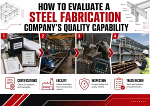
Buyers evaluating a fabrication vendor for pressure vessels, tanks, or structural equipment benefit from looking past price alone and reviewing the vendor’s actual quality capability.
- Relevant fabrication experience for the specific equipment type
- Documented quality-management procedures
- Approved welding procedures on file
- Qualified welders across the relevant processes and positions
- A working material-traceability system
- In-house or coordinated inspection capability
- NDT coordination with qualified personnel
- Calibration control for measuring and test equipment
- Consistent documentation practices
- Facility and equipment suited to the scope of work
- A defined process for handling non-conformances
- Verifiable previous project experience
- Demonstrated ability to work strictly to approved drawings and specifications
- Support in compiling final documentation and the manufacturing data book
The lowest quotation does not always represent the lowest total project cost. A lower price that leads to rework, site modification, or delayed commissioning can end up costing more than a properly controlled fabrication process from the start.
Why Fabricator Experience Matters
Consistent fabrication quality depends on coordination between engineering, procurement, production, welding, inspection, NDT, coating, documentation, and dispatch teams. A gap in any one of these links weakens the whole chain.
National Engineers & Steel Fabricators undertakes custom industrial steel fabrication based on approved drawings, technical specifications, material requirements, project-specific inspection plans, client requirements, and the applicable fabrication and testing procedures for each order.
This project-by-project approach reflects how industrial fabrication actually works: requirements differ by drawing, code, material, and service condition, and no single procedure applies identically to every job.
Conclusion
Reliable steel fabrication quality control depends on controls applied across the complete production lifecycle, not on a single inspection performed at the end of the process.
It rests on working from approved drawings, verifying materials before use, maintaining traceability, following qualified welding procedures with skilled welders, carrying out stage-wise inspection, selecting the correct NDT method, checking dimensions and coatings, testing where applicable, and keeping complete documentation through to final inspection.
Because fabrication requirements depend on the approved drawings, material specifications, applicable codes, client requirements, and service conditions of each project, no single procedure applies identically to every job.
Planning a custom steel fabrication project? National Engineers & Steel Fabricators manufactures industrial steel components and equipment based on approved drawings, material specifications, inspection requirements and project documentation. Share your fabrication scope and technical requirements with our team for further discussion.
| Disclaimer: This article is intended for general technical guidance. Final fabrication, welding, inspection, testing, coating and documentation requirements depend on the approved drawings, applicable codes and standards, material specifications, service conditions, client requirements and review by competent, authorized professionals. |
Frequently Asked Questions
Why is quality assurance important in fabrication?
Quality assurance establishes the procedures, qualifications, and controls that prevent defects before fabrication begins, such as approved welding procedures, welder qualifications, and calibration systems. Without this system in place, quality control checks have no consistent standard to verify against.
What is an Inspection and Test Plan?
An Inspection and Test Plan (ITP) is a project-specific document that defines the inspection stages, applicable drawings and procedures, acceptance criteria, responsible parties, and hold or witness points required to control quality throughout a fabrication project.
How is material traceability maintained in steel fabrication?
Material traceability is maintained by linking heat numbers on the raw material to Material Test Certificates, transferring identification marks before original markings are cut or blasted away, and keeping traceability logs and cutting plans that record which heat each finished part came from.
What is the purpose of a Material Test Certificate?
A Material Test Certificate (MTC) documents the chemical composition and mechanical properties of a specific heat of steel, allowing the fabricator and client to verify that the material used matches the specification called for in the approved drawing.
Why are WPS, PQR and WPQ important?
A Welding Procedure Specification (WPS) defines how a joint must be welded, a Procedure Qualification Record (PQR) demonstrates that the procedure produces acceptable properties, and Welder Performance Qualification (WPQ) confirms the welder can execute that procedure correctly. Together they control weld quality before production starts.
Which NDT methods are used in steel fabrication?
Common non-destructive testing methods include visual testing, dye-penetrant testing, magnetic-particle testing, ultrasonic testing, and radiographic testing. The applicable method depends on the material, joint type, expected defect type, and the project specification, and no single method detects every defect type.
Is visual inspection enough for welded fabrication?
Visual inspection is a necessary first layer of weld quality control, but it only detects surface-level issues. Where a specification requires it, additional non-destructive testing such as ultrasonic or radiographic testing is needed to check for internal defects that visual inspection cannot detect.
How is welding distortion controlled?
Welding distortion is controlled through balanced and symmetrical welding sequences, controlled heat input, fixtures and strongbacks, presetting, and correct tack-welding practice. Stage-wise dimensional checks help catch distortion early, before it becomes difficult to correct.
Why is dimensional inspection necessary?
Dimensional inspection confirms that a component meets its approved tolerances at each stage of fabrication, before errors are built into later stages or the final assembly. Catching a dimensional error early is far less costly than correcting it after welding or coating is complete.
How is coating quality checked?
Coating quality is checked through surface-profile verification before application, environmental monitoring of humidity and dew point during application, dry-film thickness measurement after application, and holiday or adhesion testing where specified in the project requirements.
What records should a steel fabricator provide?
A steel fabricator should be able to provide approved drawings, material test certificates, welding procedure and qualification records, NDT reports, dimensional inspection reports, calibration certificates, coating reports, and a final manufacturing data book compiling all of the above.
What is a non-conformance report?
A non-conformance report documents any deviation from an approved drawing, specification, or acceptance criterion found during fabrication or inspection, along with the evaluation, disposition, corrective action, and verification carried out to resolve it.
Why must measuring equipment be calibrated?
Measuring and test equipment must be calibrated because uncalibrated instruments can produce inaccurate readings that go undetected until a problem shows up later. Calibration traceable to a recognized standard ensures that recorded measurements can be trusted.
How can buyers evaluate a steel fabrication company?
Buyers can evaluate a fabrication company by reviewing its relevant project experience, documented quality procedures, welder and procedure qualifications, material-traceability system, inspection and NDT capability, calibration control, and its track record of handling non-conformances and providing complete documentation.
What are the most common steel fabrication defects?
Common defects include dimensional errors, misalignment, excessive distortion, weld cracks, porosity, undercut, lack of fusion, incomplete penetration, and coating defects such as insufficient film thickness. Most are traceable to a specific gap in an earlier fabrication or inspection stage.
When is pressure testing required?
Pressure testing requirements depend on the equipment type, applicable code, and the approved project procedure. Not every fabricated item requires pressure testing, and the specific test method, whether hydrostatic or another approach, is defined by the project’s technical requirements.
Why should stainless steel be segregated from carbon steel?
Stainless steel should be segregated from carbon steel because contact with carbon-steel tools, surfaces, or particles can embed iron contamination on the stainless surface, which can lead to localized corrosion even when the base material itself meets specification.
How does quality control reduce project costs?
Quality control reduces project costs by catching errors at the stage where they are cheapest to correct, rather than after welding, coating, or dispatch. This helps avoid rework, site modification, delayed commissioning, and disputes over non-conforming equipment.
Can quality be inspected only after fabrication is complete?
No. Inspecting only at the end allows dimensional errors, fit-up problems, and weld defects to compound across multiple stages before they are found. Stage-wise inspection throughout cutting, forming, fit-up, welding, and coating catches issues while they remain correctable.